TheDeveloperBlog.com
C-Sharp | Java | Python | Swift | GO | WPF | Ruby | Scala | F# | JavaScript | SQL | PHP | Angular | HTML
DBMS Convert ER into table
DBMS Convert ER into table with DBMS Overview, DBMS vs Files System, DBMS Architecture, Three schema Architecture, DBMS Language, DBMS Keys, DBMS Generalization, DBMS Specialization, Relational Model concept, SQL Introduction, Advantage of SQL, DBMS Normalization, Functional Dependency, DBMS Schedule, Concurrency Control etc.
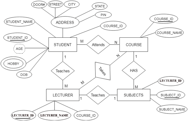
Reduction of ER diagram to TableThe database can be represented using the notations, and these notations can be reduced to a collection of tables. In the database, every entity set or relationship set can be represented in tabular form. The ER diagram is given below: 
There are some points for converting the ER diagram to the table:
In the given ER diagram, LECTURE, STUDENT, SUBJECT and COURSE forms individual tables.
In the STUDENT entity, STUDENT_NAME and STUDENT_ID form the column of STUDENT table. Similarly, COURSE_NAME and COURSE_ID form the column of COURSE table and so on.
In the given ER diagram, COURSE_ID, STUDENT_ID, SUBJECT_ID, and LECTURE_ID are the key attribute of the entity.
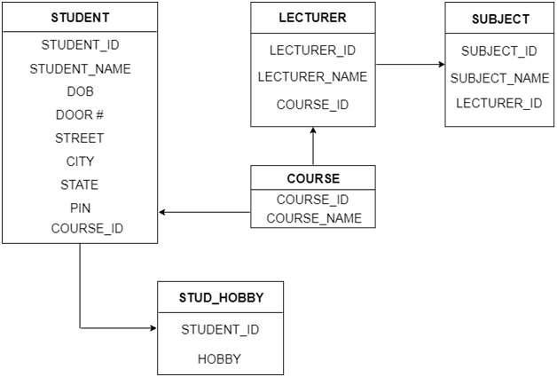
In the student table, a hobby is a multivalued attribute. So it is not possible to represent multiple values in a single column of STUDENT table. Hence we create a table STUD_HOBBY with column name STUDENT_ID and HOBBY. Using both the column, we create a composite key.
In the given ER diagram, student address is a composite attribute. It contains CITY, PIN, DOOR#, STREET, and STATE. In the STUDENT table, these attributes can merge as an individual column.
In the STUDENT table, Age is the derived attribute. It can be calculated at any point of time by calculating the difference between current date and Date of Birth. Using these rules, you can convert the ER diagram to tables and columns and assign the mapping between the tables. Table structure for the given ER diagram is as below: 
Figure: Table structure
Next TopicDBMS Relationship of Higher Degree
|
Related Links:
- DBMS Multivalued Dependency
- DBMS Inclusion Dependence
- DBMS SQL Set Operation
- Top 52 DBMS Interview Questions (2021)
- DBMS Transaction Processing Concept
- DBMS States of Transaction
- DBMS Schedule
- DBMS Conflict Serializable Schedule
- DBMS View Serializability
- DBMS Recoverability of Schedule
- DBMS Tutorial | Database Management System
- DBMS Failure Classification
- DBMS Concurrency Control
- DBMS Lock based Protocol
- DBMS Log-Based Recovery
- DBMS Checkpoint
- DBMS Timestamp Ordering Protocol
- DBMS Validation based Protocol
- DBMS Thomas Write Rule
- DBMS Multiple Granularity
- DBMS Sequential File Organization
- DBMS Recovery Concurrent Transaction
- DBMS Characteristics of SQL
- DBMS File organization
- DBMS Heap File Organization
- DBMS Hash File Organization
- DBMS B+ Tree
- DBMS RAID
- DBMS B+ File Organization
- DBMS Indexed Sequential Access Method
- DBMS Cluster File Organization
- DBMS Hashing
- DBMS Static Hashing
- DBMS Dynamic Hashing
- DBMS SQL Introduction
- DBMS Advantage of SQL
- SQL Commands: DDL, DML, DCL, TCL, DQL
- DBMS SQL Operator
- DBMS SQL Insert
- DBMS SQL Update
- DBMS SQl Datatype
- DBMS SQL Table
- DBMS SQL Select
- DBMS SQL Index
- DBMS SQL Sub Queries
- DBMS SQL Clauses
- DBMS Generalization
- DBMS Specialization
- DBMS vs Files System
- DBMS Architecture
- DBMS SQL Delete
- DBMS SQL View
- DBMS Three schema Architecture
- DBMS Data model schema and Instance
- DBMS Join Operation
- DBMS Notation for ER diagram
- DBMS Relational Calculus
- DBMS Data Independence
- DBMS Language
- DBMS ER model concept
- DBMS Mapping constraints
- DBMS Keys: Primary, Foreign, Candidate and Super Key
- DBMS Aggregation
- DBMS Join Dependency
- DBMS Convert ER into table
- DBMS Relationship of Higher Degree
- DBMS Relational Model concept
- DBMS Relational Algebra
- DBMS Integrity Constraints
- DBMS Functional Dependency
- DBMS Inference Rule
- DBMS Normalization: 1NF, 2NF, 3NF and BCNF with Examples
- DBMS Transaction Property
- DBMS Testing of Serializability
- DBMS 1NF
- DBMS 2NF
- DBMS SQL Aggregate function
- DBMS SQL Joins
- DBMS 3NF
- DBMS BCNF
- DBMS 4NF
- DBMS 5NF
- DBMS Relational Decomposition